Stage 7: Production Planning and Preparation

UpStop Wheelchair Braking System example
Background — Prior Stages
One of the most difficult tasks facing aging manual wheelchair users is the difficulty engaging or keeping engaged the wheel locks on their wheelchairs. Having a stable, non moving, wheelchair during the transfer process is of the utmost importance to all wheelchair users. The UpStop Wheelchair Braking System is designed to reduce the occurrence of falls among manual wheelchair users when they are transferring to and from their wheelchair.
The UpStop automatically engages a set of brakes separate from the wheelchair's standard wheel locks when the occupant begins to exit, thus preventing the wheelchair from rolling forwards or backwards. When entering the wheelchair, the occupant's weight is applied to a release arm located just under the wheelchair seat causing the braking system to disengage. This allows the wheelchair to move freely. When the occupant begins to exit the wheelchair, the weight is relieved from the release arm, causing the brake arm to engage. The brake arm provides a frictional force to the wheelchair tire that resists forward and backward motion. There is also a brake release mechanism, that when engaged by an attendant, disengages the braking system allowing an unoccupied wheelchair to be pushed by an attendant or caregiver.
Upon receiving a patented prototype from an inventor, our Initial scope of this project included performing a preliminary market assessment including conducting a consumer panel to verify the need for the device; a preliminary business assessment including searching for competing products and technologies; an initial technical assessment of the inventors prototype; and lastly planning on how to assist in its commercialization. Through Alpha or concept generation focus groups, consumers identified the functions and features of an ideal manual wheelchair braking system. These features were used to create the Beta prototype which was then tested by wheelchair users. Therefore a complete redesign of the inventors prototype was performed prior to introducing the prototype to potential licensing entities.
Step 7.1
Draft preliminary bill of materials (BOM): A bill of materials must be developed by the organization intending to manufacture a product in order to detail each part and subassembly and the costs associated with them. They will assign part numbers and put an inventory control system into place. As this product was to be licensed to an outside party, the RERC did not generate a fully exploded bill of materials. However, because we were shipping partial assemblies to potential licensing entities for their evaluation, our engineers drafted detailed parts and assembly instructions along with pictures and placement arrows for the various components.
Step 7.2
Develop materials plan: We provided a materials/component list for the licensing entity. All company part numbers and assembly steps were to be added by the licensing entity.
Step 7.3
Estimate market needs and costs for production: Previously, in Steps 2.2 (scoping assessments), 4.3 (building business case), and 4.11 (alpha focus groups), we estimated the market size, developed a competing product matrix and defined the true market’s needs by having consumers identify the functions and features needed for their ‘ideal’ automatic manual wheelchair braking system.
Steps 7.4 — 7.11
Develop production and capacity plan through Develop post-launch evaluation plan: Seeing how the UPStop Braking system fit into their production and capacity plans, these activities were the responsibility of the licensing entity.
Step 7.12
Initiate trial or limited production runs: For the UpStop Wheelchair Braking System, we fabricated a limited production run of 25 units for Sunrise Medical. The UpStop kits, as they were called, were shipped to Sunrise where they were given a Sunrise part number, and added into Sunrise’s inventory control system. These 25 units were to be used as trial or test units for Sunrise’s clients.
Step 7.13
Test market or trial sell: We determined the product should sell to individuals in manual wheelchairs, institutions, and retail establishments/amusement parks etc. where wheelchairs are provided as a courtesy. Sunrise Medical test marketed the device, but opted not to license. Alimed, the eventual licensee, also test marketed the device at Medtrade, a large medical device show.
Results
As mentioned above, we produced 25 UpStop units for test marketing by Sunrise Medical. To our knowledge, Sunrise made no concerted effort to try and sell these units. In the interim, as there are three primary manual wheelchair manufacturers and distributors in the United States (Sunrise Medical, Invacare, and Drive Medical), we elected to have our fabrication shop develop UpStop kits for all three wheelchair brands.
After we had designed and fabricated UpStop kits that could be used in conjunction with the major manual wheelchair brands, Alimed, a medical device manufacturer and distributor, expressed interest in the concept. Alimed licensed the patent and device and attempted to have their engineering department combine all three UpStop kits (Sunrise Medical, Invacare and Drive Medical) into one universal kit that could be used on all manual wheelchairs. As part of our licensing agreement, the inventor received guaranteed annual minimum payments as well as any additional royalties accrued for each unit sold.
After 2 years, Alimed’s engineering group determined that they were unable to design a suitable universal UpStop kit and terminated the license agreement. As shown by this case example, due to funding constraints, federally funded research and development entities cannot do everything on their own. Many steps in the production process must be undertaken by the licensing manufacturer. For purposes of licensing an invention, work completed in earlier product development stages can be leveraged downstream to justify market need, market size and desired functionality of the product.
UpStop Wheelchair Braking System for Manual Wheelchairs Assembly & Installation Instructions
Special Notes
- Please read all assembly instructions before beginning assembly.
- Please take special notice of all text in italics.
Parts List & Quantity
| Item | Description | Quantity |
|---|---|---|
| 1 | Left Assembly | 1 |
| 2 | Right Assembly | 1 |
| 3 | 1/2" OD X 1 7/8" Plastic Spacers | 2 |
| 4 | 10-24 X 3" Slotted Screws | 2 |
| 5 | 1" Washers | 4 |
| 6 | 10-24 Nylock Nuts | 4 |
| 7 | 8-32 Allen Cap Screws | 4 |
| 8 | Mounting Brackets | 2 |
| 9 | Springs | 2 |
| 10 | SAE #12 Washers | 2 |
| 11 | Small Plastic Spacers | 2 |
| 12 | 1/4-20 X 2" Allen Cap Screws | 2 |
| 13 | 1/4-20 Nylock Nuts | 2 |
| 14 | Brake Levers | 2 |
| 15 | Brake Cables with Housings | 2 |
| 16 | Cable Stabilizers | 4 |
| 17 | 10-24 Allen Cap Screws (with hole for brake cable) | 2 |
| 18 | SAE #10 Washers | 2 |
| 19 | Wheelchair Handle Extensions | 2 |
Tools Needed for Assembly
- Allen Wrench (9/64", 5/32", 3/16")
- Box End Wrenches (3/8", 7/16")
- Phillips Screwdriver
- Slotted Screwdriver

Figure 1: Parts used in Assembly of Wheelchair Braking System
Assembly Instructions
Please note: Assembly should begin from behind the wheelchair, as all of the parts are labeled "left" or "right" based on assembly from that position. Make sure all "left" parts go on the Left Assembly, and all "right" parts go on the Right Assembly. Assembly may be easier if the wheelchair is placed on top of a workbench.
Assembly Part I - Mounting Left and Right Assemblies to the Wheelchair
Parts Needed for Assembly Part I
1 — Left Assembly
1 — Right Assembly
2 — 1/2" OD X 1 7/8" Plastic Spacer
2 — 10-24 X 3" Slotted Screws
4 — 1" Washers
2 — 10-24 Nylock Nuts
4 — 8-32 Allen Cap Screws
2 — Mounting Brackets
Note: For Assembly Part I, please refer to Figures 2-5.
Step 1 — Remove the existing lever brake system from the wheelchair.
Step 2 — Locate the upper axle hole at the rear of the wheelchair. Insert one large plastic spacer into the upper axle hole so that the spacer is encapsulated. Refer to Figure 2 for location of the upper axle hole.
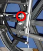
Figure 2: Location of upper axle hole with braking system attached. Upper Axle hole with 10-24 X 3" Slotted Screw marked with a red circle.
Step 3 — Take Right Assembly and remove the mounting bracket from the front mounting block.

Figure 3: Wheelchair's Plastic Support (marked with a red arrow).
Step 4 — Relocate the wheelchair's plastic support on the right side as shown in Figure 3 to the rear of the wheelchair tubing. This allows the braking system to fit properly on the underside of the wheelchair. Please Note: This does not need to be done for the left side of the wheelchair.
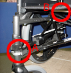
Figure 4: Positioning of Right Assembly from the front of the wheelchair. Mounting Bracket is marked with an A, Wooden Roller with a B.
Step 5 — Slide Right Assembly onto the wheelchair so that the front mounting block comes into contact with the wheelchair tubing. Make sure that the wooden rollers are positioned at the front of the wheelchair as shown. Please refer to Figures 4 and 5.
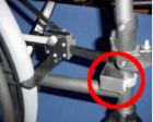
Figure 5: Positioning of Right Assembly from the side of the wheelchair (Front Mounting Block marked with a red circle).
Step 6 — Insert a 10-24 X 3" Slotted Screw with a 1" washer into the upper axle hole so that the head of the screw is on the wheel side of the wheelchair. Line up the rear mounting holes located on the Right Assembly with the 10-24 X 3" Slotted Screw currently in the upper axle hole. Insert the screw through the rear mounting holes along with a 1" washer and secure with a 10-24 Nylock nut. Refer to Figures 2 and 6.

Figure 6: Upper Axle Hole (A) and Spring Mounting Hole (B) Positioning.
Step 7 — Move around to the front of the wheelchair and find the two holes in the front mounting block. Take one of the mounting brackets and line up the holes on the front mounting block with the holes on the mounting bracket. Make sure that the mounting bracket is located above the weld flange on the wheelchair tubing. Insert an 8-32 Allen Cap Screw into each hole and secure. This fastens the mounting bracket to the system the same way it came attached initially. Please refer to Figure 4. Please Note: The front mounting block may need to be adjusted slightly before tightening down the mounting bracket as the mounting block's position affects the how the brake arm makes contact with the tire. Adjust until the brake arm makes full contact with the tire and then tighten the mounting bracket and the Allen cap screw on top of the mounting block.
Step 8 — Tighten all other fasteners on Right Assembly to ensure that everything is secure.
Step 9 — Repeat Steps 2-3 and 5-8 for Left Assembly.
Assembly Part II — Attaching the Spring to the Braking System
Parts Needed for Assembly Part II
2 — Springs
2 — SAE #12 Washers
2 — Small Plastic Spacers
2 — 1/4-20 X 2" Allen Cap Screw
2 — 1/4-20 Nylock Nut
Note: For Assembly Part II, please refer to Figures 7-8.
Step 1 — Please Note: For this step, be extremely careful when elongating the spring to prevent it from snapping back and possibly causing injury. Locate the spring already attached to Right Assembly at the spring mounting hole. Place the looped end of the spring between an SAE #12 washer and a small plastic spacer and insert the 1/4-20 X 2" Allen Cap Screw through all three parts. The SAE #12 washer should be on the wheel side of the spring. Elongate the spring so that the 1/4-20 X 2" Allen Cap Screw that was just placed through the looped end of the spring lines up with the hole in the plastic slider and insert. Please refer to Figure 7.
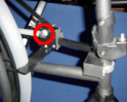
Figure 7: Completed plastic slider assembly shown from the side of the wheelchair (Spring placement on plastic slider circled).
Step 2 — On the other side of the plastic slider, insert the same 1/4-20 X 2" Allen Cap Screw into the hole at the end of the linkage. Add a 1/4-20 Nylock Nut and secure. Please Note: Do not fully tighten the 1/4-20 Nylock Nut in order to allow the linkage to move with out much friction. This is necessary for the braking system to work effectively.
Step 3 — Repeat Steps 1-2 for Left Assembly.
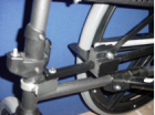
Figure 8: Completed plastic slider assembly shown from underneath the wheelchair.
Assembly Part III — Attaching the Brake Levers and Cables to the Braking System
Parts Needed for Assembly Part III
2 — Brake Levers
2 — Brake Cables with Housings
4 — Cable Stabilizers
2 — 10-24 Allen Cap Screw (with hole for brake cable)
2 — 10-24 Nylock Nut
2 — SAE #10 Washers
2 — Wheelchair Handle Extensions
Note: For Assembly Part III, please refer to Figures 9-13.
Step 1 — Remove wheelchair handle grips. It is recommended to use air pressure to remove the handle grips.
Step 2 — Slide one brake lever onto the right wheelchair handle so that the lever is on the top of the handle. Push it forward until the back part of the brake lever bracket is approximately 3/8" from the edge of the wheelchair handle. Do not tighten the brake levers down yet. Please refer to Figure 9. When the brake lever installation is completed, the cables should not come into contact with a person sitting in the wheelchair. The cables should curve down behind the chair along the interior side of the handle as shown in Figure 9.
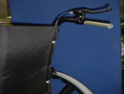
Figure 9: Positioning of brake levers and handle extension.
Step 3 — Insert the plastic end of the handle extension into the wheelchair handle. Take the previously removed wheelchair handle grips and place them all the way onto the handle extension. The brake lever may need to be moved forward slightly to allow the plastic grips to slide on. After all adjustments are made to the handle and grips, tighten down the brake lever using a 3/16" Allen wrench. Please refer to Figure 9.
Step 4 — Insert cylinder end of the cable into the top of the brake lever handle as shown in Figure 10.

Figure 10: Inserting cylinder end of cable.

Figure 11: Aligning the slots on the adjusting screw with the slot on the brake lever handle.
Step 6 — Lay the cable into the slot. Then turn the silver adjusting screw and the silver adjusting nut to close the slot over the cable.
Step 7 — Slide the cable housing into the end of the silver adjusting screw.
Step 8 — Locate the four screws securing the padded backrest to the wheelchair on each side. Remove the bottom screw and the screw second from the top along with the finish washers. The removed finish washers are no longer needed. Take two of the cable stabilizers and attach them to the brake cable so that they line up with the holes created by removing the screws. Insert the same screws back into the two holes and tighten. Make sure that the cable is on the interior when attaching the cable stabilizers to the chair and the cable housing is up tight against the silver adjusting nut. Please refer to Figure 12.

Figure 12: Orientation of Cable Stabilizer.
Step 9 — Take the end of the cable and slide it through the hole in the 10-24 Allen Cap Screw. Insert the 10-24 Allen Cap Screw into the hole at the end of the release arm on the wheel side of the chair. Secure with a 10-24 Nylock nut on the other side of release arm. Please refer to Figure 13.
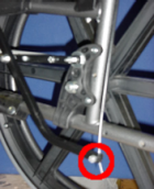
Figure 13: Fully assembled brake lever cable (Hole on release arm for attaching brake cable circled).
Step 10 — Pull down on the brake lever to see if the brake arm releases adequately. Most likely, the cable length may need to be readjusted slightly at the bottom so that the cable is taut. Loosening the 10-24 Nylock nut and pulling the cable down as far as possible and then retightening will accomplish this. If needed, very minor adjustment can be made to the cable at the brake lever. This adjustment will allow the brake to have optimum release.
Step 11 — Repeat Steps 2-10 for the left side.
Step 12 — Tighten all hardware on the entire braking system to ensure that it is secure. Make sure that any hardware used at a pivot point (at both ends of the linkage and where the release arm attaches to the mounting bar) is not over tightened to allow adequate space for the parts to be able to rotate.
